Cut Top and Bottom Base
The upper base of the mount is made from a thin sheet of plastic. It should be as light as possible so the stilts don't droop too much. In this case we use the lid from a Pringles can.
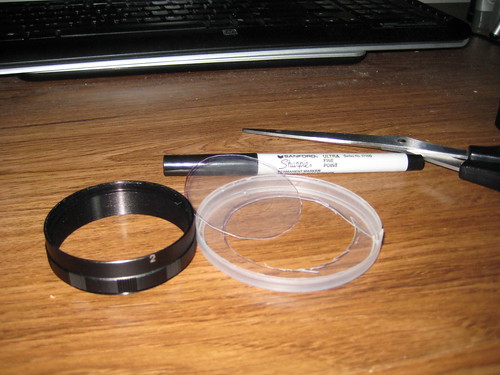
Use a fine point marker to draw the inner ring from the #2 ring. You want this to be narrower than the inner diameter of the tube. This will allow it to move without hitting the wall of the tube. It can be rough and still work. Use a pair of scissors to cut it out. Try dropping it within the tube. If it falls through then it is good enough.
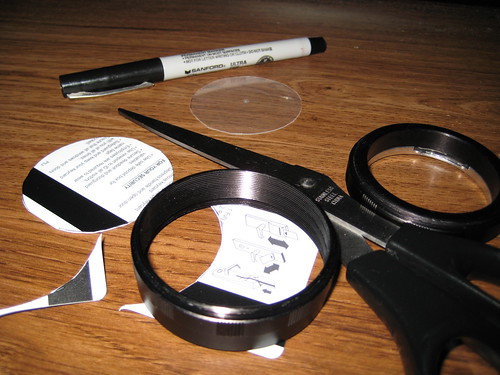
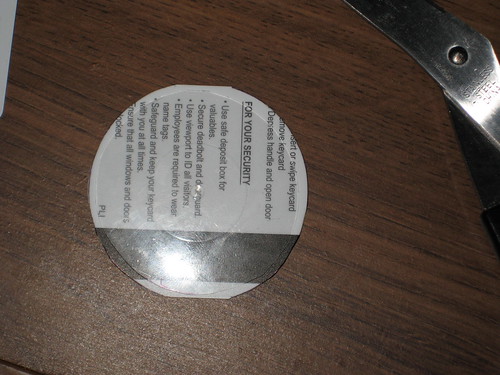
The bottom part will fit between the F-mount ring and the 2nd ring. Trace the inner diameter of the #2 tube for this. Getting it exactly is best. The #2 ring has a gap between the inner wall and the thread wall that attaches to the next ring. This is where this mount will be held fast. Again use the marker to draw the circle. Since its a card there the top and bottom may be cut off. That's fine. Cut with your scissors.
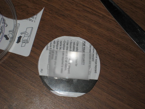
With both bases cut, stack them on top of each other to get the relative center. We need to mark the window for the Canon Ee-A focus screen. Use some isopropyl alcohol to clean your fingers before handling. You want the matte side up. You can tell by comparing both sides against the light. Another clue is the big tab on the focus screen is on the right when matte side up. You can mark the edges with a fine point sharpie or with the box cutter.
Set aside the focus screen and bottom base. Take a box cutter/knife and straight edge. Apply firm pressure on the top base and make a box window. It works best to apply lots of downward pressure to make the cut. The window should be very slightly smaller than the focus screen to make mounting easier later.
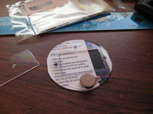
Once the window is cut, put it over the bottom base and trace the inner window onto the bottom base. Also mark out where the three stilts should be. Leave about 2mm from the sides of the window. Then about four for the top. The bottom won't have a stilt but have a motor instead. This is just a fit test. Don't glue anything together yet!
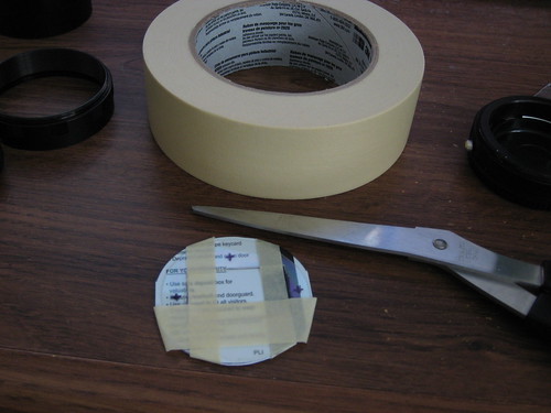
Use masking tape to fix the two pieces together. Please don't use cellophane tape or electrical tape as a substitute. The adhesives on those tend to leave a residue.
What's next?
We'll start drilling and gluing to make our initial static mount.
No comments:
Post a Comment