Sunday, April 29, 2007

Building a PVC Figrig for Camcorder Stabilization

I've been looking for a compact way to stabilize my walking and 35mm footage. The monopod is great for static shots but sways too much at the head while walking. A DIY steadicam is a bit too heavy to be taking around casually. My search led me to a DIY figrig by shygantic which in turn led me to the more compact version by webstr.


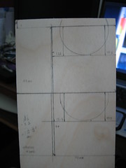
My parts list was a bit different from the original. I'm short a coupler. Only after building it did I realize that his had a 90 degree elbow and a 45 degree elbow whereas mine used two 90 degree elbows.

My Part list
2 x 1/2" SCH40 90-degree PVC Conduit Elbow (Electrical)
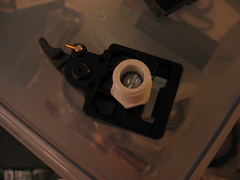
1 x 1/2" SCH40 90-degree PVC elbow with threaded side outlet (Plumbing)
6 x 1/2" SCH40 45-degree PVC elbow Slip-type (Plumbing)
8 x 1" of 1/2" SCH40 PVC (Plumbing -- usually sold in 10")
1 x 1/2" SCH40 Threaded Plug (Plumbing)
1 x 1-1/2" Wing screw (-20 Machine screw)
1 x 3/4" SCH40 (-20 Machine screw)
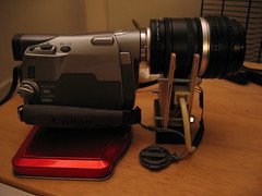
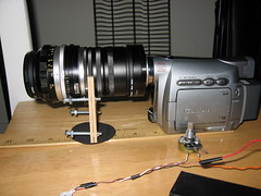
1 Bogen/Manfrotto 3299 Quick Release Adapter

Tools and Consumables
1 roll of electrical tape
1 roll of teflon tape
1 drill with 1/4" bit
1 mitre box
1 hacksaw
1 can of PVC cement and primer
1 Mask
1 Pair of Gloves

The hardest part to find was the 1/2" 90 degree elbow with side outlet. I had to search three Home Depot and two Lowes stores to find it. And it was by chance since it was mixed in with the 3/4"x3/4"x1/2" kind. If you're stuck with that, you can probably use reducing bushings to bring it down to 1/2". Or you could scale bigger so all the parts are common.

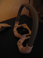
You cut the pipe to make 1" connectors then dry fit the rig to your liking. I used a marker to draw lines indicating alignment. Once happy with that I started gluing (actually solvent welding -- primer first, glue next) from the center of the design out. This helps keeping the entire thing balanced. If you've not worked with PVC cement before, make sure to do it in an open spot with a mask on. Use gloves. You apply the purple primer on one both connecting sides to melt the PVC. Then the glue is applied on top of both. Fit the parts together and hold for a few seconds. Clean up the excess goop with cardboard or plastic. Make sure the alignment is correct while its still soft. The cement dries quickly so glue half the connector to each fitting in sections. The rig will smell for days and isn't fully dried until 24 hours later.

The last piece to go in was the top handle bar and the threaded plug. The 1/4" drill bit was used to make a hole in the plug and handle bar for screw mounts. The 3/4" screw went to the threaded plug for the QR adapter. Teflon was used around the plug thread to help put it in. It doesn't go all the way in! Halfway is good enough as long as it is secure. The 1-1/2" wing screw went to the handle bar for the microphone base.

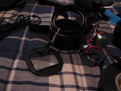
What about the electrical tape? PVC gets brittle under long term exposure to sunlight. So I wrapped it in electrical tape for that NOT PLUMBING look.

References:
Shygantic figrig http://www.flickr.com/photos/shygantic/129121710/
Webstr figrig http://www.flickr.com/photos/wbstr/357975178/

Friday, April 20, 2007

How to adjust your 35mm Footage

Most of my footage comes out washed out or too dark. Blame it on my amateur manual skills. But it turns out all is not lost. To get the missing detail out of the footage there are tools.


NLEs and programs such as Virtual Dub and Avisynth allow you do to color curves and color correction. Eyeball and S-curve, adjust the gamma, and the contrast then you're on your way. Of course these values change once you recompress to a different format (e.g. when you upload to Youtube).

Sites with Tips:
http://www.wideopenwest.com/%7ewvg/tutorial-1.htm

Tuesday, April 17, 2007

Static Adapter Version 2

I broke my vibrating motor while disassembling it from the 52mm tube. I had constructed a ground glass holder by cutting up a plastic key card and slipping it into an empty 52mm filter ring. Mounted backwards it mated with a 52mm-to-52mm macro coupler. Unfortunately it didn't work because there wasn't enough play to vibrate the ground glass. Incidentally, the test tape was somehow lost as I changed tapes. And later I had an accident that broke one of the small gauge wires on the motor. I get knocked down, but i get up again.

So I took the 52mm filter plus mount I made for the failed vibrating experiment and moved it to the 57mm. Incidentally a 52mm filter fits snug in that macro tube so it was easy to position and get to the right distance. Add a +10 singlet macro and some step down and I was in business. This was also the perfect chance to try my brand spanking new camcorder.


Say hello to the Canon HV20. It's a small HDV camcorder with a progressive CMOS sensor. The little wonder reminds me of my Canon Elura which was one of few early MiniDV with a progressive CCD. Against all advise, I hooked up my Static Adapter to both the ZR200 and HV20. Their resolution and light gathering abilities are different. I just wanted to see how bad the grain could be with this unit. One other thing changed on the V2, I have a +10 singlet close-up macro (not an achromat). The shot was done indoors on a cloudy day.


Lens: 50mm Nikon Series E f/1.8
DOF Adaptor: YouSillyMan35 v2 Static, Nikon F3 Type D
Camera: Canon HV20, 1/2.7" Single CMOS progressive
Original Mode: HDV24PF, TV-48
Recompression: WMV9 1920x1080 30fps progressive, 6Mbps
File Size: 71.24MB
http://www.megaupload.com/?d=9G3EUNE5

Lens: 50mm Nikon Series E f/1.8
DOF Adaptor: YouSillyMan35 v2 Static, Nikon F3 Type D
Camera: Canon ZR600, 1/6" Single CCD interlaced
Original Mode: DV interlaced, automatic
Recompression: WMV9 720x480 29.97fps interlaced, 4Mbps
File Size: 45.84MB
http://www.megaupload.com/?d=3N8MNZ2B

Saturday, April 14, 2007

How not to do a Vibrating Ground Glass

The static is fine for web videos but leaves much to be desired for full DV. At low light like indoors shooting the grain shows up around the edges. So I try to convert the simple static to a full vibrating ground glass. Unfortunately I am not successful yet.


Notice something wrong? The adapter was a full centimeter short! One of the spacers is too short. This wreaked havoc with the infinity focus.


I started with the 52mm tube and cutout a plastic card. I carefully cut a rectangle the size of the Nikon Type D for mounting the ground glass. I tried it alone inside of the tube as a static but it wasn't stable. So I try using a 52mm filter in reverse and that held the ground glass well. Trial fitting the motor I found that there wasn't much room to mount it vertically as it should. So just for kicks I try it horizontal. It doesn't work.


Not one to give up, I sacrifice some of the focus screen's visible area by mounting the motor vertically against the fastening tab on the Nikon Type D. The vibrations are more quiet but I can't see the grain moving. There isn't enough play in the rectangular cutout nor the plastic card to allow the grains to move.

I ask the kind folks at DVInfo Alternative Imaging what kind of stupidity I've delved into and I'm told that my arrangement wouldn't work. The horizontal was moving in the wrong direction. It was also loud because it was turning the card into a diaphragm. Meanwhile my vertical was too tight on the tube to allow the movement necessary to blur the grain. Just for kicks I'm taking the vertical setup to the seaport for some test shots.

Converting a 57mm Macro Tube to a 58mm

To convert my macro tube I elected to use spacer 1. To prepare the pieces the spacer was cleaned with soapy water then dried. Same for the filter ring after the glass and retainer were removed. Once dried I started mixing the two part epoxy. I used JB Weld for its strength and 15 minute setting time. Anything from 15 to 30 minutes is good. The faster epoxies tend to become brittle especially with exposure to sun. And never use cyanoacrylate glue such as Super Glue/Mighty Bond/Krazy Glue. The fumes from this glue is the same used by forensic investigators to lift fingerprints from evidence. Keep those away from optics.


The finished product ready to accept 58mm


The epoxy will be a soft goop but shouldn't run. Make sure its as close to a 1:1 ratio. Now apply the epoxy with a disposable blade or a credit card to the male thread of the spacer. Apply a small amount to the inner thread of the filter. Be careful not to get any on the inner thread of the spacer and the rear thread of the filter. Use a stable surface to put the two together. Press and turn to even it out.

Epoxy will probably be spilling out the inside and the side. Use a blade or credit card to scrape the excess out. If any get on a thread, use a wet towelette or your fingers to wipe (make sure you wash your hands before eating!). On a stable flat surface, hold the assembly to the light to make sure they are lined up. Cleaning may protrude part of the filter outside of the spacer's ring. Just push slightly in whatever direction to adjust.

Set the assembly aside in a warm undisturbed place overnight. After the setting time has elapsed it's ready.

Friday, April 6, 2007

Other ways of aligning the Groundglass


When using a paper strip make sure it's stiff enough to stand


Use a toothpick or a strip of paper marked with 46.5mm to adjust the distance of the ground glass.

Thursday, April 5, 2007

The Right Way to Remove Glass from a Filter

I was ready to go destroy the glass on this sacrificial 58mm filter. Then looking at it I wondered how they go it in there in the first place. It certainly wasn't using glue.


There is a retaining ring that holds the glass to the filter. On either side is a tab. The tabs are where you apply pressure and turn the ring counter clockwise. This unscrews the retainer. To remove it I used the art foam-screw driver technique. Placing the filter on the foam prevents skidding. I then use one of my little fingers to press the ring down on the foam to lock it in place. With a set of flat head precision screw drivers I rotate the ring counter-clockwise. This unlocks the ring and allows me to use one screw driver from then on.


If you don't want to do those contortions, find yourself a pair of circlip pliers that can go to the proper diameter. McMaster-Carr calls them retaining clip pliers. There is also a spanner version which are locking. They have two teeth like a protractor that will hold the tabs as you spin it. Speaking of which, a drawing compass may be easier to find.

Wednesday, April 4, 2007

Limitations of The Static Adapter

Besides the grain, the other thing you will notice immediately with a static adapter is how much cleaning you have to do. Even very small pieces of lint or dust can ruin your image if it lands on either the ground glass or condenser. I made the mistake of using the pad end of a lenspen to clean the ground glass and now there is this little black spec embedded in one of the very small pits. Use air, brush, and microfiber cloth to clean your groundglass.


The dust speck is on the lower left quadrant when rotated 180 degrees. Two more fibers of lint next to it which got muddled by YouTube's compression.

The static adapter is small and light. But the attached lens isn't. I'm using a Non-AI 50mm Nikkon S-C which is about as heavy as the entire camcorder. It must be conceded that the ZR200 is a featherweight as camcorders go, but that totally makes balance different. Learning to frame and hold the image takes a bit of practice. And did I mention that the camcorder's image stabilization won't help you because the SLR lens is doing the work? Live and learn. But it's fun. While taking this video a passerby asked me "Is that a camera or video? How much does it cost?" My answer, "I just put it together myself."

Making a support system

The whole assembly is front heavy. The new center of gravity makes handling the camcorder awkward especially for such a small unit. It also puts a lot of stress on the camcorder's lens thread. There are support systems that can be purchased commercially but I want to give it a shot myself.

Parts:

1) Plywood
2) 1/4-20 machine screws
3) Glue

Tools:

1) Mechanical pencil
2) Metric ruler
3) Screw drivers
4) Dremel minisaw / Handsaw
5) Boxcutter

I start out with the leftover plywood from the spinner project. Plywood is easier to work with than plastic unless you are able to make your own molds or have access to a CNC machine. Cardboard is another possibility but that isn't as sturdy.

First I measure the distance from camcorder base to bottom of the 58mm tube assembly. Then get an additional measure up to the middle. Then I draw two rectangles of the dimensions I want on the plywood. Now for the decision.


I want to make this unit a vibrating gg later on so I need room to mount switches and batteries. So I decided on a two piece holder braced with screws, hence the two rectangles. Within a box defining the bottom of the assembly to the middle I trace the outer diameter of the tube.

I cut the two pieces out with a saw. Its a rough cut which needs to be sanded even (I prefer to use dremel to get it close then handsand for accuracy). For the half-circle cut out, I use a cutting blade and dremel cutting tool to make a rough cut. Then I sand it down with the rotary sander by hand until it's even. Before you go off to do this, make sure you are away from your optics and either have a mask or open air. Lots of sand dust is produced from power sanding! It helps to have some sort of vise to hold the wood or drill screws into the two pieces to sand them together.