This is the fourth in the series of instructions on how to build the YSM35B Vibrating 35mm DOF Adapter. In the last part we started to cut the base parts of the mount. Here we finish building the static part of the mount.
Finish the Mount as Static
Watch the video because its easier to explain that way.
We start by drilling holes on the two plastic base holders where previously marked. If you don't have a rotary tool and a press you can use a regular drill. Just set it to its lowest setting. Failing that you can find something sharp and round like a precision screw driver to poke a hole. Use a drill bit that has a sharp end so it doesn't catch on the plastic and try to spin it. Something slightly smaller than a 1/8" bit is good for these syringe plungers.
It wasn't shown in the video but between drilling the holes and mounting the plungers I cut out the opening on the bottom base. Use a metal straight edge and a sharp knife. It will take multiple cuts to break through. Work on top of cardboard or a stack on newspapers to avoid scratching your table or floor.
Now that the holes are done its time to put the base on stilts. Take your syringe plungers and cut off the push tabs with a knife. Fit the rubber plunger through the bottom base (plastic card). You might have to slip it in a slant then rotate it to get it all the way in. Repeat to get all three stilts on. Then slip the top base (pringles lid) on top. Don't worry if stilts appear slightly skewed. It will still work.
Mount the assembled mount on top of the F-mount then screw on ring #2. Measure about 50-60mm from the front of the F-mount and the end of the plungers. Cut off with scissors or cutter from pliers. The mount won't look as wonky after this.
Get ready to glue on the Ee-A focus screen. Before doing that, make sure to clean your fingers with isopropyl alcohol. Also identify which side is matte. You can hold it against the light and tilt it slightly to compare. One side will be more reflective. The Ee-A has a big tab. If this tab is upper left or lower right you have the matte side up. I like to have the tab located lower right. It doesn't matter which way you have it.
Adjust the base so its about 45mm from the flange (front edge) of the F-mount. When the focus screen is set it will be near the right distance for infinity. It won't be perfect yet but it will be close enough for now.
Rest the focus screen matte side up on the top base. Carefully align the edges and hope it doesn't fall off. If you cut off too much material for the window you might have to hold it while you glue the edges. Time to plug in the hot glue gun.
The glue gun needs about 3-5 minutes to heat up. When you glue, pull away from the focus screen. This ensures the left over glue threads don't land on the screen. The glue gun leaves strands of glue as you pull away, use your fingers to cut them.
Let it cool for about 5 minutes. Now it is safe to handle. You can screw the #3 and #1 macro tube rings on. See how much clearance the top mount has to the wall. It's okay if they touch on some points. It just makes it noisy. You can cut at the touch points to increase clearance.
At this point you have a static 35mm adapter!
Why did we do this?
The rubber on the plungers allows the top base to vibrate freely while limiting the vibration transmitted to the adapter body. Yes, the top base making contact with the inner wall of the macro tube will introduce some vibration. Shaving the contact points will reduce that. Syringe plungers were used because these are relatively easy to get. Any strong yet flexible material can be used as long as you can attach it to the Nikon F-mount.
What's next?
Setting the focal plane to correct distance prior to making it a vibrating unit.
Saturday, November 15, 2008

YSM35B Building the Vibrating Mount Part 2
This is the third in the series of instructions on how to build the YSM35B Vibrating 35mm DOF Adapter. In the last part we went through the theory of the vibrating mount. In this part we build it.
Cut Top and Bottom Base
The upper base of the mount is made from a thin sheet of plastic. It should be as light as possible so the stilts don't droop too much. In this case we use the lid from a Pringles can.

Use a fine point marker to draw the inner ring from the #2 ring. You want this to be narrower than the inner diameter of the tube. This will allow it to move without hitting the wall of the tube. It can be rough and still work. Use a pair of scissors to cut it out. Try dropping it within the tube. If it falls through then it is good enough.

The bottom part will fit between the F-mount ring and the 2nd ring. Trace the inner diameter of the #2 tube for this. Getting it exactly is best. The #2 ring has a gap between the inner wall and the thread wall that attaches to the next ring. This is where this mount will be held fast. Again use the marker to draw the circle. Since its a card there the top and bottom may be cut off. That's fine. Cut with your scissors.

With both bases cut, stack them on top of each other to get the relative center. We need to mark the window for the Canon Ee-A focus screen. Use some isopropyl alcohol to clean your fingers before handling. You want the matte side up. You can tell by comparing both sides against the light. Another clue is the big tab on the focus screen is on the right when matte side up. You can mark the edges with a fine point sharpie or with the box cutter.

Set aside the focus screen and bottom base. Take a box cutter/knife and straight edge. Apply firm pressure on the top base and make a box window. It works best to apply lots of downward pressure to make the cut. The window should be very slightly smaller than the focus screen to make mounting easier later.

Once the window is cut, put it over the bottom base and trace the inner window onto the bottom base. Also mark out where the three stilts should be. Leave about 2mm from the sides of the window. Then about four for the top. The bottom won't have a stilt but have a motor instead. This is just a fit test. Don't glue anything together yet!

Use masking tape to fix the two pieces together. Please don't use cellophane tape or electrical tape as a substitute. The adhesives on those tend to leave a residue.
What's next?
We'll start drilling and gluing to make our initial static mount.
Cut Top and Bottom Base
The upper base of the mount is made from a thin sheet of plastic. It should be as light as possible so the stilts don't droop too much. In this case we use the lid from a Pringles can.
Use a fine point marker to draw the inner ring from the #2 ring. You want this to be narrower than the inner diameter of the tube. This will allow it to move without hitting the wall of the tube. It can be rough and still work. Use a pair of scissors to cut it out. Try dropping it within the tube. If it falls through then it is good enough.
The bottom part will fit between the F-mount ring and the 2nd ring. Trace the inner diameter of the #2 tube for this. Getting it exactly is best. The #2 ring has a gap between the inner wall and the thread wall that attaches to the next ring. This is where this mount will be held fast. Again use the marker to draw the circle. Since its a card there the top and bottom may be cut off. That's fine. Cut with your scissors.
With both bases cut, stack them on top of each other to get the relative center. We need to mark the window for the Canon Ee-A focus screen. Use some isopropyl alcohol to clean your fingers before handling. You want the matte side up. You can tell by comparing both sides against the light. Another clue is the big tab on the focus screen is on the right when matte side up. You can mark the edges with a fine point sharpie or with the box cutter.
Set aside the focus screen and bottom base. Take a box cutter/knife and straight edge. Apply firm pressure on the top base and make a box window. It works best to apply lots of downward pressure to make the cut. The window should be very slightly smaller than the focus screen to make mounting easier later.
Once the window is cut, put it over the bottom base and trace the inner window onto the bottom base. Also mark out where the three stilts should be. Leave about 2mm from the sides of the window. Then about four for the top. The bottom won't have a stilt but have a motor instead. This is just a fit test. Don't glue anything together yet!
Use masking tape to fix the two pieces together. Please don't use cellophane tape or electrical tape as a substitute. The adhesives on those tend to leave a residue.
What's next?
We'll start drilling and gluing to make our initial static mount.
Wednesday, November 12, 2008
YSM35B Building the Vibrating Mount Part 1
This is the second in the series of instructions on how to build the YSM35B Vibrating 35mm DOF Adapter. You should have modified your Asian Macro Tube to have a 58mm thread by now.

Building the Vibrating Mount
This is the core of the adapter so there will be more detail. The main parts and tools needed:
Canon Ee-A focus screen
3pcs syringe plungers (type used for insulin)
Hot glue gun with sticks
Mechanical Pencil
Plastic card
Scissors
Box cutter or any sharp blade
Metric Ruler
2 solid core wires
Vibrating motor
Drill
Soldering Iron
The Theory
Before we begin lets get some background out of the way. A 35mm adapter needs a condenser and ground glass. In our case the Canon Ee-A focus screen is both in a small package. This tiny piece of plastic has a matte side and a more transparent side. The matte side is what we will use as the ground glass. This side faces to the back of the adapter. The other side is a fresnel pattern that faces to the front. It serves as a condenser, not a great one but better than nothing, to capture the light from the 35mm lens to brighten it up on the ground glass.
Normally, the ground glass needs to be held 46.5mm away from the F-mount on the adapter. But the fresnel piece changes the optics a bit so it should be closer by a few millimeters. We'll adjust this by eye later. If you have access to a collimator then good for you. If you could build one then I applaud you!
Assuming the distance of the focus screen is right, the 35mm lens set on infinity should have a sharp picture for far away objects. This would mean the focus marks on the lens would be fairly accurate as well.
With the above parts this is a static adapter. For daylight this is usually fine with fast lenses. The more you stop down on the lens the grain on the focus screen becomes more visible. There are ways to blur this out in software or you could eliminate this with hardware. To remove the grain you could oscillate or rotate the ground glass. In our case we will use a small vibrating motor to oscillate it.
What's next?
We'll start cutting our initial static mount in the next post.
Building the Vibrating Mount
This is the core of the adapter so there will be more detail. The main parts and tools needed:
Canon Ee-A focus screen
3pcs syringe plungers (type used for insulin)
Hot glue gun with sticks
Mechanical Pencil
Plastic card
Scissors
Box cutter or any sharp blade
Metric Ruler
2 solid core wires
Vibrating motor
Drill
Soldering Iron
The Theory
Before we begin lets get some background out of the way. A 35mm adapter needs a condenser and ground glass. In our case the Canon Ee-A focus screen is both in a small package. This tiny piece of plastic has a matte side and a more transparent side. The matte side is what we will use as the ground glass. This side faces to the back of the adapter. The other side is a fresnel pattern that faces to the front. It serves as a condenser, not a great one but better than nothing, to capture the light from the 35mm lens to brighten it up on the ground glass.
Normally, the ground glass needs to be held 46.5mm away from the F-mount on the adapter. But the fresnel piece changes the optics a bit so it should be closer by a few millimeters. We'll adjust this by eye later. If you have access to a collimator then good for you. If you could build one then I applaud you!

Assuming the distance of the focus screen is right, the 35mm lens set on infinity should have a sharp picture for far away objects. This would mean the focus marks on the lens would be fairly accurate as well.
With the above parts this is a static adapter. For daylight this is usually fine with fast lenses. The more you stop down on the lens the grain on the focus screen becomes more visible. There are ways to blur this out in software or you could eliminate this with hardware. To remove the grain you could oscillate or rotate the ground glass. In our case we will use a small vibrating motor to oscillate it.
What's next?
We'll start cutting our initial static mount in the next post.
YSM35B Asian Macro Tube to 58mm Thread
This is the first in the series of instructions on how to build the YSM35B Vibrating 35mm DOF Adapter based on the parts lists of the YSM35(A). The build will be nearly the same except I'll be using a 58mm Opteka HD^2 Macro plus a smaller power pack.
At the end of this series you will know how you could build one yourself. Or know enough about how one is built to diagnose problems with your existing adapter.

Putting a 58mm Thread on the Nikon Macro Tube
For this part we'll recap how to modify an "Asian Macro Tube" with Nikon F Mount to have a standard 58mm filter ring. You will need the following items:
Asian Macro Tube with Nikon F-mount
58mm UV Filter
Two Part Epoxy (e.g. JB Weld)
2 Flat Head precision screw drivers (or a drawing compass)
Paperclip
Plastic Card
Isopropyl Alcohol
Use a non-slip pad to remove the glass from the UV filter. We only want the ring to convert the 57mm tube to 58mm. Use the two screwdrivers or compass (the drawing tool not the magnetic direction finder) to twist the inner ring counterclockwise. Applying downward pressure helps. This will unfasten the ring. Once you have it out remove this retaining ring and the glass.

Take the Asian Macro and find the "1" ring. Set the rest side. You can discard the ring with the bayonet mount. Clean both the filter thread and the "1" ring with isopropyl alcohol. Set aside.
Mix the two part epoxy on a piece of carton or paper with a paper clip. JB Weld is good. There is a white and black tube. The black one is harder to get the contents out. You will get a grey goop. Apply the goop to the rear thread of the "1" ring. Make sure to have some all around. Then stack the 58mm filter on top of this. The epoxy may get squeezed out on the sides and the inside between the threads.
Press and hold for a few seconds. While the goop is still soft use the plastic card to scrape the excess from the outside. Inspect the front inner thread of the "1" ring and the rear outer thread of the 58mm filter. Clean out any goop on it. Allow this to cure for 24 hours. It will cure faster in warm weather.
Why did we do this?
The Asian Macro tube is the body for the adapter. The ones off Ebay were 1mm too small. We need a standard 58mm thread to attach a macro, circular filter, and 43mm to 58mm step up ring later.
What is next?
The next post will be about how to build the vibrating mount.
At the end of this series you will know how you could build one yourself. Or know enough about how one is built to diagnose problems with your existing adapter.
Putting a 58mm Thread on the Nikon Macro Tube
For this part we'll recap how to modify an "Asian Macro Tube" with Nikon F Mount to have a standard 58mm filter ring. You will need the following items:
Asian Macro Tube with Nikon F-mount
58mm UV Filter
Two Part Epoxy (e.g. JB Weld)
2 Flat Head precision screw drivers (or a drawing compass)
Paperclip
Plastic Card
Isopropyl Alcohol
Use a non-slip pad to remove the glass from the UV filter. We only want the ring to convert the 57mm tube to 58mm. Use the two screwdrivers or compass (the drawing tool not the magnetic direction finder) to twist the inner ring counterclockwise. Applying downward pressure helps. This will unfasten the ring. Once you have it out remove this retaining ring and the glass.
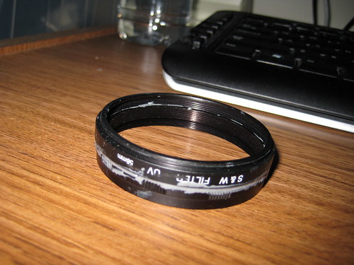
Take the Asian Macro and find the "1" ring. Set the rest side. You can discard the ring with the bayonet mount. Clean both the filter thread and the "1" ring with isopropyl alcohol. Set aside.
Mix the two part epoxy on a piece of carton or paper with a paper clip. JB Weld is good. There is a white and black tube. The black one is harder to get the contents out. You will get a grey goop. Apply the goop to the rear thread of the "1" ring. Make sure to have some all around. Then stack the 58mm filter on top of this. The epoxy may get squeezed out on the sides and the inside between the threads.
Press and hold for a few seconds. While the goop is still soft use the plastic card to scrape the excess from the outside. Inspect the front inner thread of the "1" ring and the rear outer thread of the 58mm filter. Clean out any goop on it. Allow this to cure for 24 hours. It will cure faster in warm weather.
Why did we do this?
The Asian Macro tube is the body for the adapter. The ones off Ebay were 1mm too small. We need a standard 58mm thread to attach a macro, circular filter, and 43mm to 58mm step up ring later.
What is next?
The next post will be about how to build the vibrating mount.
Wednesday, October 15, 2008
YSM35 Usage Guide and Test Footage
Guide to using and setting the YSM35 Vibrating Adapter. Just for reference.
I discuss how to adjust manual focus with the HV20 and other general usage notes for a 35mm adapter. This video was made for my brother who is now the user of my first successful vibrating adapter.
Note that the Bower 58mm Singlet has been replaced with a 52mm Opteka HD^2 +10 Macro.
Handheld Test Video
I discuss how to adjust manual focus with the HV20 and other general usage notes for a 35mm adapter. This video was made for my brother who is now the user of my first successful vibrating adapter.
Note that the Bower 58mm Singlet has been replaced with a 52mm Opteka HD^2 +10 Macro.
Handheld Test Video
Sunday, May 11, 2008
Vibrating 35mm DOF adapter completed
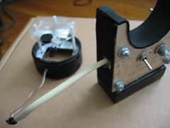
After almost a year I get back to completing my vibrating adapter. This time I switched the ground glass from the Nikon F3 Type D to a Canon Ee-A focus screen. I made a holder out of three syringe plungers, a key card, and the lid from a can of pringles chips. I kid you not, it's that ghetto. But it works. The pancake motor and motor controls are reused from the previous attempt. The assembly seems to work well.


Parts Currently Used
1 Canon Ee-A focus screen (Canon USA Part#YN2-3558-000)
1 "Asian" Macro Extension Tube with Nikon Mount (ebay)
2 58mm Filters (ebay)
1 58mm Bower +10 Singlet Macro (ebay)
1 Lid from a Pringles can (corner store-any flavor!)
1 Key card (in my pocket-any flat plastic will do)
3 Syringe plungers (generous individual)
1 43-55 Step-Up ring (ebay)
1 55-58 Step-Up ring (ebay)
1 2xAA Battery Holder (Radioshack)
2 AA Batteries (supermarket)
1 40-ohm Rheostat (radioshack)
1 2-way flip switch (radioshack)
1 splice of wire (old CAT5 works)
1 RG-45 connector (from an old telephone)
1 RG-45 socket (from a DSL suppressor)
4 machine screws (Home Depot)
12 machine nuts (Home Depot)
1 plank of plywood (Michael's craft store)
Tools Used
1 two-part epoxy (for asian tube to 58mm)
1 Dremel (for cutting the holder)
1 Carbide tip (for cutting the holder)
1 Drill with various small drillbits
1 Boxcutter
1 Scissors
1 Soldering Iron
1 spool of Solder wire
1 nail clipper
1 magnifying lens
2 rulers
1 mechanical pencil
1 hot-glue gun
1 roll of electrical tape
1 packet of heat shrink tubing
I'll have to explain the build and post sample footage in a later post. It's going to be a long story. And be careful when trying to source those syringe plungers. Apparently some states won't let you buy them without a prescription. I tried getting it over the counter once and I was given odd looks. I forget that insulin syringes might also be used for other drug applications thus these could be regulated where you live. There are alternatives such as nylon screws or carbon fiber wires.
Parts Currently Used
1 Canon Ee-A focus screen (Canon USA Part#YN2-3558-000)
1 "Asian" Macro Extension Tube with Nikon Mount (ebay)
2 58mm Filters (ebay)
1 58mm Bower +10 Singlet Macro (ebay)
1 Lid from a Pringles can (corner store-any flavor!)
1 Key card (in my pocket-any flat plastic will do)
3 Syringe plungers (generous individual)
1 43-55 Step-Up ring (ebay)
1 55-58 Step-Up ring (ebay)
1 2xAA Battery Holder (Radioshack)
2 AA Batteries (supermarket)
1 40-ohm Rheostat (radioshack)
1 2-way flip switch (radioshack)
1 splice of wire (old CAT5 works)
1 RG-45 connector (from an old telephone)
1 RG-45 socket (from a DSL suppressor)
4 machine screws (Home Depot)
12 machine nuts (Home Depot)
1 plank of plywood (Michael's craft store)
Tools Used
1 two-part epoxy (for asian tube to 58mm)
1 Dremel (for cutting the holder)
1 Carbide tip (for cutting the holder)
1 Drill with various small drillbits
1 Boxcutter
1 Scissors
1 Soldering Iron
1 spool of Solder wire
1 nail clipper
1 magnifying lens
2 rulers
1 mechanical pencil
1 hot-glue gun
1 roll of electrical tape
1 packet of heat shrink tubing
I'll have to explain the build and post sample footage in a later post. It's going to be a long story. And be careful when trying to source those syringe plungers. Apparently some states won't let you buy them without a prescription. I tried getting it over the counter once and I was given odd looks. I forget that insulin syringes might also be used for other drug applications thus these could be regulated where you live. There are alternatives such as nylon screws or carbon fiber wires.
Sunday, April 27, 2008
Making a Bottle Cap Stabilizer
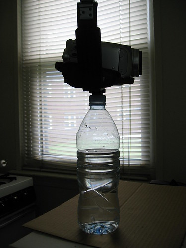
Bottle caps for stabilizers? Yeah, it might look silly but it could be convenient. Pick a common threaded bottle cap. Poke a screw through it. Put some washers and a nut in to expose just a small bit of thread. Fill the bottle with fluid or sand and you've got yourself a pendulum to stabilize your lightweight camera. It also makes for a very low on the ground tripod.

Bottle Cap Stabilizer

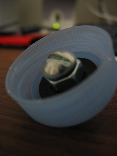
Top View of Bottle Cap Mount

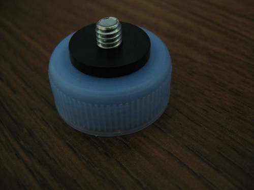
Bottom View of Bottle Cap Mount
Parts:
1 Bottle Cap
1 3/4" long 1/4"-20 Screw (usually where you find locks and door knobs)
1 1/4"-20 Nut (usually where you find locks and door knobs)
2 1/2L Flat Faucet Washer (usually near plumbing with sinks and faucets)
Tools:
Drill
1/4" Drill Bit
1/8" Drill Bit
Screwdriver
Find a bottle cap you want to use. Mark the center. Use the smaller 1/8" drill bit to make a pilot hole. I use a big cardboard box so I don't worry about making holes on my workbench. Then expand the hole with the 1/4" drill bit. Clean out the center.
Take the 3/4" 1/4-20 screw then thread the nut through to the base. Take one of the 1/2L washers (O.D. 25/32") and thread the screw into it. The inner diameter of the washer is smaller than the screw. So you may have to set it down a table and screw down with the screw driver. Then it's a matter of hold the washer as you screw it flush against the nut. Take the screw-nut-washer piece and thread that though the bottom of the bottle cap. Once completely through, thread it into the second washer. Both washers should hold the cap tight. This way you can thread the entire thing. You might want to use a third washer or some other spacer depending on how shallow the mount screw is on your camera.
Fill the bottle with some sort or fluid or sand. Anything that will give it weight and keeps the bottle pointing to the ground would do. Then you've got a cheap stabilizer. If the bottle cap is common enough (like from bottled water or soda) you don't have to bring the body with you. Just buy your drink wherever you are and thread your camera in. You might get some looks but who cares if it makes your camera more stable.
Parts:
1 Bottle Cap
1 3/4" long 1/4"-20 Screw (usually where you find locks and door knobs)
1 1/4"-20 Nut (usually where you find locks and door knobs)
2 1/2L Flat Faucet Washer (usually near plumbing with sinks and faucets)
Tools:
Drill
1/4" Drill Bit
1/8" Drill Bit
Screwdriver
Find a bottle cap you want to use. Mark the center. Use the smaller 1/8" drill bit to make a pilot hole. I use a big cardboard box so I don't worry about making holes on my workbench. Then expand the hole with the 1/4" drill bit. Clean out the center.
Take the 3/4" 1/4-20 screw then thread the nut through to the base. Take one of the 1/2L washers (O.D. 25/32") and thread the screw into it. The inner diameter of the washer is smaller than the screw. So you may have to set it down a table and screw down with the screw driver. Then it's a matter of hold the washer as you screw it flush against the nut. Take the screw-nut-washer piece and thread that though the bottom of the bottle cap. Once completely through, thread it into the second washer. Both washers should hold the cap tight. This way you can thread the entire thing. You might want to use a third washer or some other spacer depending on how shallow the mount screw is on your camera.
Fill the bottle with some sort or fluid or sand. Anything that will give it weight and keeps the bottle pointing to the ground would do. Then you've got a cheap stabilizer. If the bottle cap is common enough (like from bottled water or soda) you don't have to bring the body with you. Just buy your drink wherever you are and thread your camera in. You might get some looks but who cares if it makes your camera more stable.
Subscribe to:
Posts (Atom)